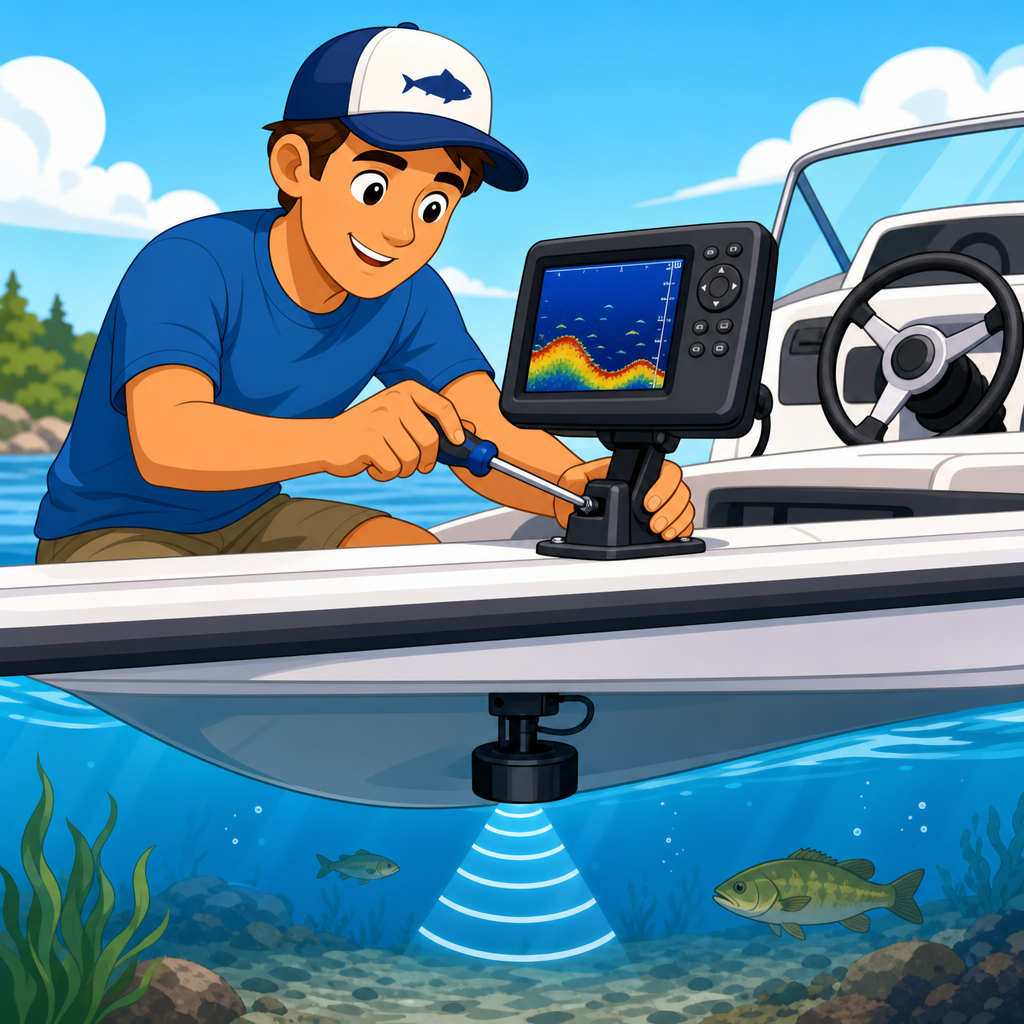
Installing a depth finder on your boat is one of the smartest upgrades you can make for safer navigation, better fishing, and more confident boat handling. A depth finder is an electronic instrument that uses a transducer to send sound waves into the water and measure how long the echo takes to return from the bottom. That data is displayed as depth, and on many modern units it also reveals bottom contour, structure, water temperature, and even fish targets. In practical terms, it helps you avoid grounding, locate channels, read drop-offs, and understand what is beneath the hull before it becomes a problem.
Within boating gear and equipment, electronics and navigation systems form the decision-making layer of the boat. Life jackets keep people afloat and anchors hold position, but electronics tell you where you are, what is around you, and what the water is doing under the hull. I have installed depth finders on aluminum fishing boats, center consoles, and trailerable cruisers, and the same lesson comes up every time: a good unit only performs as well as the installation. Poor transducer placement, undersized wiring, weak connections, and rushed calibration cause more problems than the head unit itself. A careful install solves those issues from the start.
This hub article explains how to install a depth finder on your boat while also showing where the device fits inside the broader category of marine electronics. If you are comparing fish finders, chartplotters, VHF radios, GPS antennas, AIS, radar, or autopilot components, depth sensing is often the first system to add because it is affordable, immediately useful, and foundational for navigation. The sections below cover choosing the right style of unit, selecting a mounting location, wiring safely to marine standards, positioning the transducer correctly, testing the system, and understanding when to link the depth finder with other navigation tools.
Choose the Right Depth Finder for Your Boat and Use Case
The first step is matching the unit to the boat, the hull material, and the type of water you run. Small freshwater boats often use compact fish finder style displays from Garmin, Humminbird, or Lowrance. Coastal and offshore boats may use dedicated sounder modules or multifunction displays that integrate sonar, GPS mapping, and radar. If your primary goal is navigation in shallow water, a simple digital depth readout with an audible shallow-water alarm may be enough. If you also fish, you will want CHIRP sonar, down imaging, or side imaging, depending on budget and target species.
Transducer choice matters as much as the display. Transom-mount transducers are common on outboard boats because they are affordable and straightforward to install. Through-hull transducers provide stronger performance at speed and in offshore conditions, but installation is more invasive because it requires drilling the hull and bedding the fitting properly. In-hull or shoot-through-hull transducers work on many solid fiberglass hulls and avoid exterior drag, but they cannot read through aluminum, wood, cored laminates, or hulls with trapped air voids. Before buying anything, confirm compatibility between the display, sonar frequency range, and transducer connector standard.
For a hub-level view of electronics and navigation systems, it helps to think of the depth finder as one sensor in a network. A standalone unit can work perfectly well, but many owners eventually want shared waypoints, NMEA 2000 data, chart overlays, engine integration, or DSC radio position sharing. If you expect that expansion, choose a unit with networking support now rather than replacing it later. I have seen owners save a little money on an entry-level screen, then spend much more upgrading when they add a chartplotter or heading sensor. Planning for integration prevents duplicate purchases.
Plan the Installation Before You Drill Anything
A clean installation starts with planning cable routes, power supply, and physical mounting points. The display must be visible from the helm, protected from direct impact, and reachable without stretching across the wheel or throttle. Check behind the mounting surface for steering components, harnesses, fuel lines, and structural supports before drilling. On smaller consoles, I often tape the bracket in place and sit at the helm to verify sightlines in both seated and standing positions. Glare, switch interference, and wheel clearance are easier to fix before holes exist.
Power should come from a properly protected marine circuit, not from random accessory wires twisted together behind the dash. Most manufacturers specify a voltage range and recommend connecting directly to the battery or to a clean electronics bus through the correct fuse. Marine-grade tinned copper wire, adhesive-lined heat-shrink terminals, and waterproof cable support are not optional details. They are what prevent voltage drop, corrosion, and intermittent shutdowns. The American Boat and Yacht Council guidance on circuit protection and conductor support is worth following because marine environments punish shortcuts fast.
You also need a realistic plan for the transducer cable. Manufacturers generally warn against cutting or splicing transducer cables because impedance changes and shielding problems can degrade sonar performance. That means the existing plug has to pass through every rigging chase, console opening, and bulkhead opening on the route. Measure the path, check bend radius, and use proper grommets or cable clams where the cable passes through fiberglass or aluminum. If the route crosses VHF antenna coax, trolling motor power cables, or engine ignition harnesses, maintain separation where possible to reduce electrical noise on the screen.
Install the Display and Run Marine-Grade Power Correctly
Once the layout is confirmed, mount the display according to the manufacturer template. Bracket mounts are easy to service and ideal for smaller boats. Flush mounts look cleaner and reduce snagging, but they require more precise cutting and enough depth behind the panel. Use a center punch on metal, drill pilot holes first, and seal exposed core material on composite panels if the cut edge reveals wood. Stainless hardware is standard, but use backing washers or a backing plate on thin panels so vibration does not elongate the fastener holes over time.
For wiring, install the specified fuse close to the power source, not behind the display. This protects the full length of the positive conductor. Keep negative returns on a proper bus or direct battery negative rather than sharing unknown grounds with noisy pumps or accessories. I prefer labeling both ends of every new conductor because future troubleshooting always happens in poor light when multiple red wires look identical. If your boat already has a fuse block dedicated to electronics, confirm it has enough amperage capacity and that the feed wire size supports the added load.
Marine displays are sensitive to voltage sag during engine cranking. On boats with marginal batteries, the screen may reboot when starting the outboard. That is not usually a bad depth finder; it is a power quality problem. The fix can be as simple as cleaning battery terminals, separating house and start loads, or using a dedicated electronics battery in larger systems. A digital multimeter should show whether voltage at the unit remains within spec under load. Stable power is the baseline requirement for every navigation system, from a simple depth sounder to a full multifunction display suite.
Mount the Transducer in the Right Location
Transducer placement determines whether the depth finder works reliably at idle only or keeps reading when the boat is on plane. On a transom-mount install, the transducer should sit where it remains in clean, non-aerated water. That usually means close to the centerline but offset enough to avoid trailer bunks, steps, strakes, rivet lines, and the propeller wash. On single-outboard boats, many installers place it on the starboard side because clockwise prop rotation can create a cleaner water path there, though hull design always overrides rules of thumb. The bottom face must usually be level with or slightly below the hull bottom, following the manufacturer angle guidance.
Through-hull installations require more precision. Deadrise angle affects the fairing block and the transducer beam alignment. A unit mounted at the wrong angle may still show depth, but the returns will be weaker and bottom tracking at speed can suffer. On stepped hulls, aerated water can make even premium transducers underperform if the location is wrong. In-hull transducers need a solid fiberglass section free of coring and voids; I test the spot with a temporary water bag or petroleum jelly coupling before epoxying anything permanently. That quick test can save hours of rework.
| Transducer Type | Best For | Main Advantage | Main Limitation |
|---|---|---|---|
| Transom mount | Outboard boats, small fishing boats | Affordable and easy to install | More exposed to turbulence and impact |
| Through-hull | Offshore boats, high-speed performance | Strong readings at speed and depth | Requires hull drilling and careful bedding |
| In-hull | Solid fiberglass hulls | No exterior drag or exposed hardware | Not compatible with all hull materials |
When fastening a transom transducer bracket, seal every hole with a marine sealant appropriate for the hull material. On cored transoms, overdrill, seal the core, and redrill the pilot hole to reduce water intrusion risk. Route the cable upward immediately after the transducer to create a drip loop, then secure it at intervals so vibration does not chafe the jacket. Avoid overtightening the pivot screws because fine angle adjustment during water testing is common. Many failed installations are not true failures; they simply need small vertical or angular corrections after the first sea trial.
Test, Calibrate, and Integrate with Other Navigation Systems
After installation, test the unit at the dock first. Confirm power-up, menu access, depth reading, temperature reading if equipped, and alarm operation. Set keel offset correctly if you want the display to show water depth below the keel or below the transducer rather than raw depth from the sensor. That setting matters in shallow water. A two-foot error can be the difference between a safe passage and grounding. If the unit offers frequency selection, sensitivity, noise rejection, and scroll speed, start with automatic settings, then refine them on the water based on manufacturer recommendations.
The real test happens across different speeds and bottom conditions. Idle in known depth, then accelerate gradually while watching whether bottom lock holds. If depth drops out on plane, the transducer is likely in turbulent water, too high, misaligned, or affected by spray and strakes. If the screen shows clutter, inspect cable routing and power quality before blaming the sonar. Nearby trolling motors, poorly grounded pumps, or radio transmissions can introduce interference. I troubleshoot by changing one variable at a time: angle, height, sensitivity, and then cable separation. Methodical testing reveals the actual cause faster than guessing.
As the hub for electronics and navigation systems, this topic extends beyond installation into smart integration. A networked depth finder can feed depth data to a multifunction display, sound shallow-water alarms across the helm, and combine with chartplotter mapping for route awareness. On some systems, sonar logs can help build detailed contour maps for fishing lakes. Pairing depth information with GPS, radar, AIS, and a VHF radio creates a more complete safety picture, especially in fog, at night, or in unfamiliar tidal water. Install your depth finder carefully, keep the wiring marine-grade, and treat it as the foundation of a reliable navigation setup. Then test it often, learn what a normal return looks like on your hull, and use that knowledge to boat with more confidence.
Frequently Asked Questions
What tools and materials do I need to install a depth finder on my boat?
Most depth finder installations are straightforward if you gather the right tools and parts before you begin. In addition to the depth finder display and transducer that come with the unit, you will usually need a drill, drill bits, a screwdriver, marine-grade sealant, a tape measure, zip ties or cable clamps, a pencil or marker for layout, and basic hand tools such as wrenches or pliers. If you are wiring the unit directly to your boat’s electrical system, it is also smart to have marine-grade wire, heat-shrink connectors, a fuse holder if one is not included, and a crimping tool. Using marine-grade components matters because they are built to handle moisture, vibration, and corrosion far better than standard automotive parts.
You should also check whether your boat type requires any special hardware. For example, a transom-mounted transducer on a fiberglass fishing boat is a common setup, while aluminum hulls, trolling motors, and in-hull installations may call for different brackets or mounting methods. Reading the manufacturer’s installation guide before drilling any holes is essential, because depth finder brands often specify ideal transducer placement, wire routing limits, and fuse size. Taking a little extra time to prepare your tools and verify compatibility will make the installation cleaner, safer, and much more reliable on the water.
Where is the best place to mount the transducer for accurate depth readings?
Transducer placement is the most important part of the entire installation because even a high-quality depth finder will perform poorly if the transducer is mounted in the wrong location. On most transom-mounted setups, the goal is to place the transducer where it stays in clean, undisturbed water while the boat is moving. That usually means mounting it slightly off the centerline of the transom, away from strakes, rivet lines, steps, intakes, livewell pickups, or anything else that can create turbulence or air bubbles. Turbulent water interferes with the sonar signal and can cause weak readings, bottom loss at speed, or inaccurate depth information.
The transducer should also be mounted at the proper height and angle according to the manufacturer’s directions. In general, the face of the transducer needs to sit level with the waterline when the boat is at rest, and low enough to maintain contact with solid water flow when underway, but not so low that it creates excessive drag or risk of impact. If you have a trailer boat, be sure the transducer location will not hit rollers, bunks, or the ramp during loading and unloading. For boats with stepped hulls or unique running surfaces, placement becomes more technical, and consulting the manual or a marine electronics installer may be worthwhile. Good placement is what allows the depth finder to deliver consistent readings for navigation, bottom tracking, and fish finding performance.
How do I wire a depth finder safely and correctly?
The safest and most dependable way to wire a depth finder is to connect it to a clean, properly fused power source using marine-grade wire and connectors. Many boat owners run the unit directly to the battery or to a dedicated electronics bus to reduce electrical interference and ensure stable voltage. The positive lead should include the correct fuse size recommended by the manufacturer, and the negative lead should return to the proper grounding point or battery negative terminal. Avoid tapping into old, overloaded accessory wiring if possible, because voltage drops and noise from pumps, lights, or ignition components can affect sonar performance and unit reliability.
As you route the power and transducer cables, keep them neat, supported, and protected from sharp edges, heat sources, and moving parts. It is best to separate sonar and power cables from high-current wires when possible to minimize interference. Use cable clamps or zip ties to secure the run, but do not overtighten them around sensitive transducer cables. Any connections exposed to moisture should be sealed with heat-shrink marine connectors for long-term durability. Before finalizing the installation, power the unit on and verify that the display starts properly, reads depth, and does not reset when other boat equipment is switched on. A careful wiring job not only protects the electronics, but also helps ensure clear sonar performance every time you launch.
Can I install a depth finder myself, or should I hire a professional?
Many boat owners can absolutely install a depth finder themselves, especially if the boat has a simple layout and the unit uses a standard transom-mount transducer. If you are comfortable measuring, drilling, routing wires, and making clean electrical connections, this is a very manageable do-it-yourself project. The key is to go slowly, follow the manufacturer’s instructions exactly, and double-check all mounting and wiring decisions before making permanent holes. For a basic installation, patience and attention to detail matter more than advanced technical skill.
That said, hiring a professional can be a smart choice in certain situations. If your boat has a complicated hull design, limited access behind panels, multiple electronic systems, or you are installing a more advanced sonar unit with networking, GPS integration, side imaging, or thru-hull transducers, professional installation can save time and prevent costly mistakes. A poorly mounted transducer or incorrectly wired display can lead to unreliable readings, leaks, electrical problems, or reduced performance at speed. If you are unsure about drilling into the hull or connecting to the electrical system, getting expert help is often worth it. The best choice comes down to your confidence level, your boat’s design, and how critical flawless performance is for the way you use your boat.
How do I test and troubleshoot a newly installed depth finder?
After installation, the first step is to test the unit at the dock or ramp to confirm that it powers on and recognizes the transducer. Make sure the display settings are configured correctly, including the proper transducer type if the unit requires manual setup. Once the boat is in the water, verify that the depth reading appears stable while idling. You should also look for water temperature and bottom return if your model provides those features. A successful dockside test tells you the transducer is functioning and the wiring is at least basically correct.
The next stage is on-water testing at different speeds. If the unit reads well at idle but loses bottom when you accelerate, the transducer is often mounted too high, slightly out of level, or in turbulent water. If you see erratic readings, electrical interference, or frequent screen noise, inspect the power source, grounding, cable routing, and nearby electronics. If the display does not power on at all, check the fuse, battery voltage, switch panel, and all wire connections. Also inspect the transducer cable for pinches or damage, because sonar cables should never be cut or modified unless the manufacturer specifically allows it. Fine-tuning after the initial installation is normal, and small adjustments in transducer angle or height can make a major difference in performance. A properly tested depth finder gives you dependable depth information, better awareness of bottom changes, and more confidence whether you are navigating shallow water or searching for productive fishing structure.